

Crushing Chamber Design and Output Particle Size in Stone Processing
Every ton of aggregate that leaves a crushing plant has been shaped by what happened inside the crushing chamber. Rock enters the feed opening, moves through a narrowing space, breaks under compression or impact, and exits at a size set by the machine’s design and settings. The finished product must meet specific size requirements for concrete, asphalt, road base, drainage stone, or fill. When it does, the plant runs profitably and customers receive material they can rely on. When it does not, the result is off-spec stockpiles, extra handling, and lost production.
The crushing chamber is central to that outcome, but it does not work alone. Chamber geometry determines how rock moves and how it contacts the working surfaces. Feed size and material characteristics influence how evenly the chamber fills and how rock breaks. The stone crusher setting sets the upper limit on output size and affects throughput and machine load. Wear gradually changes the chamber’s shape, and with it, the product. Screens separate crushed material into size ranges and return oversize pieces for further processing. Sampling and testing then confirm whether the finished aggregate meets project requirements.
Chamber Geometry and Rock Movement
The crushing chamber is the space where rock is reduced in size. Its shape guides material from the feed opening toward the discharge point and controls how rocks contact one another and the machine’s working components. Chamber design differs by crusher type, but the principle is the same: a carefully engineered geometry produces predictable breakage.
Chamber design must match the intended material and operating range. A chamber profile built for coarse primary crushing will not produce fine aggregate efficiently, and a fine profile fed with oversized rock may block, bridge, or overload the machine. Many manufacturers offer several liner or chamber options for the same crusher so the machine can be configured for the product required. Select the configuration based on feed size, rock type, and target output, and confirm it against the manufacturer’s application guidance.
How the chamber fills also matters. In many cone crushers, maintaining a full, choke-fed chamber encourages rock-on-rock crushing, which can improve particle shape and use the chamber’s full capacity. An irregular or starved feed can lead to uneven wear and less consistent output. Follow the manufacturer’s recommendations for feed level and feed distribution for the specific machine.
Key takeaway: Chamber geometry controls how rock moves, how it contacts crushing surfaces, and how it breaks, so select a chamber configuration that matches the feed material, operating range, and target product.
Crusher Setting and Output Size
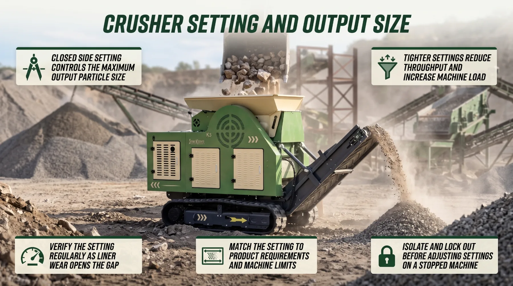
The crusher setting is one of the most direct controls an operator has over output size. Where applicable, the operating gap at the discharge determines the largest pieces that can leave the crushing zone and strongly influences the overall product gradation.
A wider setting moves the balance the other way, generally increasing capacity and reducing load while producing coarser material. The right setting is the one that produces the required product at a sustainable load and throughput, not simply the smallest or largest available.
Actual output also depends on rock properties and machine condition. Two crushers set to the same CSS may produce different gradations if they are processing different rock, running at different feed levels, or operating with different amounts of liner wear. The setting defines the gap, but the rock and the chamber determine how material breaks within it.
Settings should be adjusted only as the manufacturer permits. Many crushers use hydraulic or mechanical systems for setting adjustment, and some allow adjustment during operation while others require the machine to be stopped. Follow the operating instructions exactly, and never attempt an adjustment method the manufacturer does not approve. Where the setting must be measured or changed with the machine stopped, isolate it according to the lockout procedure, relieve hydraulic pressure where required, and confirm all moving components have come to a complete stop before working near the chamber. Use the manufacturer’s approved method for verifying the setting rather than improvised measurement techniques.
Check the setting regularly. As crushing surfaces wear, the actual gap at the discharge opens, and output becomes coarser even though no adjustment was made. Many operations verify the setting at the start of each shift or at defined intervals and compensate for wear as the manufacturer recommends.
Key takeaway: The crusher setting sets the upper limit on output size and affects throughput, load, and wear, so choose a setting that balances product requirements with machine limits and adjust it only by the manufacturer’s approved method.
Feed Size and Material Characteristics
The crushing chamber can only perform as well as the material it receives. Rock size, hardness, moisture, and shape all influence how material enters the chamber, how it moves through it, and how it breaks. Understanding the feed is often the fastest way to explain changes in output.
Feed size is the starting point. Every crusher has a specified maximum feed size based on its feed opening and chamber design. Oversized feed can restrict entry, bridge across the opening, or create blockages that stop production. Even when large rocks enter the chamber, they may cause excessive loads, uneven wear, or surging as they work their way down.
Feed gradation matters as much as top size. A feed with a balanced range of sizes tends to flow steadily and fill the chamber evenly. Feed with too many fines can pack into the chamber, reduce capacity, and in some crushers increase loads and wear. Feed with too few smaller pieces can leave voids in the chamber and reduce rock-on-rock breakage. Highly variable feed, alternating between coarse and fine material, may produce inconsistent output.
Never attempt to dislodge a bridged rock or clear a blocked feed opening by hand, by climbing into the hopper, or while the crusher and feeder can operate. Stop the equipment, isolate it according to the lockout procedure, and follow the manufacturer’s approved clearing method. Rocks and material in a hopper can shift suddenly, and feeders and crushers hold significant stored energy.
Key takeaway: Feed size, gradation, hardness, moisture, and shape all affect material flow and output consistency, so keep feed within the machine’s specified limits and as uniform as practical.
Wear Parts and Particle Consistency
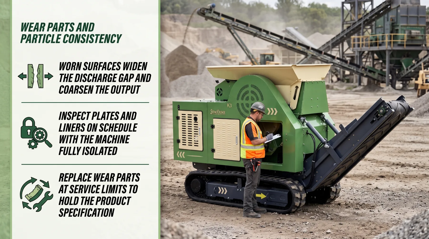
Crushing surfaces wear every hour the machine runs. Jaw plates, mantles, concaves, liners, blow bars, hammers, and aprons are all designed to wear and be replaced. As they wear, they change the shape of the chamber, and a changed chamber produces a changed product.
Uneven wear patterns often point to an underlying problem. Wear concentrated on one side of a cone crusher may indicate off-center feed. Heavy wear in one area of a jaw plate may reflect a feed size or gradation that does not suit the chamber. Blow bars that wear unevenly can point to uneven feed distribution across the rotor width. Correcting the cause extends wear part life and improves product consistency.
All inspections during crushing operations must be carried out with the machine stopped and isolated according to the lockout procedure. Never enter or reach into the crushing chamber while the machine can move. Rotors, flywheels, and eccentric assemblies can continue turning after shutdown, and loose rock in the chamber can shift. Confirm that all components are at rest and secured before beginning work.
Replace parts when they reach service limits and confirm that installed components match the specified configuration. Installing a liner profile intended for a different application, or mixing worn and new components incorrectly, can change chamber geometry in ways that affect both output and machine protection. Some wear parts can be rotated or reversed to extend their life; follow the manufacturer’s instructions for when and how to do so. Tighten fasteners to the torque values in the service manual, and use designated lifting points and approved equipment when handling heavy wear parts.
Tracking wear over time supports consistent production. Recording operating hours, tonnage, and product gradation alongside wear measurements helps maintenance teams predict replacement intervals, order parts in advance, and understand how wear affects the product at each stage of a liner’s life.
Key takeaway: Worn or damaged crushing surfaces change chamber geometry and output, so inspect wear parts with the machine fully isolated, replace them at service limits, and confirm every installed component matches the specified configuration.
Screening and Oversize Material
The crusher reduces rock, but screens sort it. After material leaves the chamber, a screen separates crushed material into size ranges by passing it over decks fitted with openings of specific sizes. Material smaller than the opening passes through, while larger material travels across the deck and discharges separately.
A screen separates material by size, but it does not change the size of each rock already crushed. If the crusher produces too much oversize, the screen can remove it from the product, but that material still needs somewhere to go. If the crusher produces too many fines, the screen can separate them, but it cannot turn fines back into larger aggregate.
When recirculating loads run high, the cause is often upstream: an open crusher setting, worn liners, unsuitable feed, or a chamber configuration that does not match the product. Correcting the crusher’s output is usually more efficient than increasing recirculation.
Screen performance depends on condition and configuration. Inspect screen media for holes, tears, and worn openings, since a damaged panel allows oversize into the product. Watch for blinding, where fine or wet material coats the openings, and pegging, where particles lodge in the openings. Both reduce open area and screening efficiency. Check that feed spreads evenly across the deck width, that the screen is not overloaded, and that vibration, angle, and stroke settings follow the manufacturer’s guidance.
Keep the screening and conveyor arrangement compatible with the crusher’s output and avoid overloading downstream equipment. A crusher producing more tonnage than the screen can process will send unscreened material into product piles or cause spillage at transfer points.
Screen maintenance requires the same safety discipline as crusher maintenance. Stop and isolate the screen and associated conveyors before changing media, clearing blinded decks, or removing lodged material. Never stand on or reach into a screen deck while it can vibrate, and use the manufacturer’s approved access points and fall protection where required.
Key takeaway: Screens separate material by size but cannot change crushed particle sizes, so use screening to control product gradation while correcting excessive oversize at the crusher rather than relying on heavy recirculation.
Measuring Finished Aggregate
Settings, chamber configurations, and screen arrangements all aim at one goal: aggregate that meets the project’s requirements. The only way to confirm that goal has been met is to measure the finished product using suitable sampling and testing methods.
A single piece does not represent the entire output. Crushed aggregate contains a range of particle sizes, and material often segregates as it moves along conveyors and settles in stockpiles. Larger particles tend to roll to the edges and base of a cone-shaped pile, while finer material concentrates near the center and top. A handful taken from one spot can give a misleading picture of the whole product.
Gradation is typically measured through sieve analysis, where the sample passes through a stack of sieves with progressively smaller openings. The material retained on each sieve is weighed, and the results are expressed as the percentage passing each size. Depending on the product, testing may also include measurements of particle shape, such as flat and elongated particles, along with fine content and other properties.
Compare results with the project’s aggregate requirements. Specifications usually define acceptable ranges for the percentage passing each sieve size, not a single target value. Track results over time rather than reviewing each test in isolation. A gradual trend toward coarser material may indicate liner wear, while sudden changes often point to a feed variation, a damaged screen panel, or a setting change.
Make one change at a time where possible and resample afterward, so the effect of each adjustment can be confirmed. Record every test result, the conditions at the time of sampling, and any adjustments made. These records support quality control, help explain trends, and demonstrate that the product meets requirements.
Key takeaway: Use representative sampling and recognized testing methods to measure finished aggregate, compare results with project requirements over time, and correct deviations through approved setting, feed, wear, or screening adjustments.
Conclusion
Crushing chamber design is one factor in determining output particle size, but feed conditions, wear, settings, and screening also matter. Chamber geometry controls how rock moves and breaks, so the configuration must match the feed material and target product. Consistent feed within the machine’s specified limits supports steady flow and predictable output, while the crusher setting defines the upper limit on product size and balances gradation against throughput and machine load. Wear gradually reshapes the chamber, making regular inspection and timely replacement essential to holding a specification. Screens sort crushed material and manage oversize through recirculation, though they cannot correct particle sizes the crusher has already produced. Representative sampling and testing then confirm whether the finished aggregate meets requirements and show where adjustments are needed. Throughout every inspection, adjustment, and sampling task, proper isolation and lockout procedures protect the people doing the work. When you monitor the full processing line and treat each of these factors as part of one connected system, your operation can produce an aggregate that consistently meets the intended size requirements.
FAQs
Does a smaller crusher setting always increase production?
No. It may create finer material while reducing throughput or increasing machine load. A tighter setting restricts how quickly material exits the chamber, raises crushing forces, and can accelerate wear. The best setting produces the required product at a load and throughput the machine can sustain.
Why does output size change during operation?
Feed variation, worn components, changing settings, and inconsistent material flow can affect the product. Liner wear gradually opens the effective discharge gap, changes in rock hardness or moisture alter how material breaks, and an uneven or starved feed changes how the chamber fills. Regular setting checks and gradation testing help identify the cause.
Can a screen control particle size?
A screen separates material by size, but it does not change the size of each rock already crushed. It can remove oversize from the finished product and send it back for further crushing in a closed-circuit plant, but correcting excessive oversize or fines usually requires adjustments at the crusher or feed.
Should chamber settings be adjusted during operation?
Only if the machine’s operating instructions allow it and the adjustment can be made safely. Some crushers are designed for adjustment while running, while others must be stopped, isolated, and locked out first. Always use the manufacturer’s approved adjustment method and never improvise.